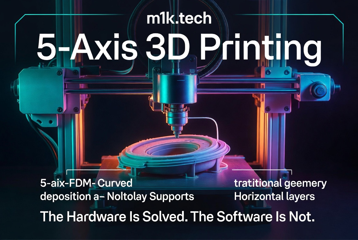
Every consumer FDM printer built in the last decade runs on the same constraint: layers are flat, horizontal, and stacked bottom-to-top. The nozzle moves in X and Y while the bed or gantry steps in Z. People call this “2.5D printing” rather than true 3D printing, and they’re right to do so, because the deposition path is always planar. You’re building a 3D object out of stacked 2D slices, not depositing material along arbitrary curves in space.
Anyone who has printed complex parts knows the two consequences. Geometry that overhangs more than about 45 degrees from vertical needs support structures, which is wasted material you have to rip off afterward, often leaving rough faces and sometimes wrecking the part on the way out. And because the layer boundaries always sit perpendicular to Z, the weakest axis of the part is always vertical. FDM parts delaminate along layer lines under tensile or shear loads in the Z direction, and you can crank infill and wall count all you like; the anisotropy stays.
5-axis FDM goes after both at the root by bolting two rotational degrees of freedom onto the motion system. The nozzle no longer has to point straight down, the bed no longer has to sit flat, and its orientation can shift continuously during the print. That frees the deposition direction to follow the part’s geometry, the stress field it will see in service, or the surface normal of a curved substrate.
The “5-axis” label comes straight from CNC convention. Three linear axes (X, Y, Z) pick up two rotational ones, usually called A and B (rotations around X and Y), or B and C, depending on the build. That gives the toolhead and workpiece six relative degrees of freedom, five of which you control and one of which (rotation around the tool axis) doesn’t matter for a round nozzle.
Two mechanical approaches have shaken out in real hardware. The first tilts the build platform. The bed sits on a mechanism that can pitch in two axes while the nozzle stays a conventional 3-axis gantry, so all the rotational mess lives under the part. The TOP.E R1 pulls this off by driving its heated bed off three independent Z-axes, tilting the plate on demand. The printhead stays simple and rigid, which is the whole appeal. The catch is that the part gets heavier as it grows and ends up cantilevered on a tilting surface, which invites dynamic load and vibration, and the effective build volume shrinks once you account for the tilt envelope. The second approach places the rotation in the toolhead itself and leaves the bed either stationary or moving conventionally. Now the part stays put, but you’ve moved real complexity to the hotend: flexible filament paths, cable management for a rotating assembly, and rigidity you can lose right at the nozzle.
Both share a single calibration requirement that determines whether either of them works. The pivot point of the rotational axes has to be nailed down in software. CNC people call it the Tool Center Point, the point around which rotations happen. If the software’s idea of where that pivot lives doesn’t match the metal, every rotational move smears in a positional error, and the errors compound with angular travel. Measure carefully, compensate iteratively, repeat. Any machinist who has done 5-axis work recognizes this on sight, because it’s exactly what makes 5-axis CNC setup so much nastier than 3-axis, even though the extra axes are mechanically trivial.
Support elimination falls out of this almost prettily. In standard FDM, an overhang exists because the nozzle always sits above the part, and gravity defines “below.” Tilt the platform, and “below” gets redefined relative to the nozzle. A feature that overhangs at 60 degrees in the part’s final orientation can be scheduled to print. At the same time, the bed is tilted so that the overhang faces up, with the nozzle always laying material onto solid material directly beneath it, no matter how the part is globally oriented. For parts with internal channels, organic shapes, or interlocking features, supports in standard FDM can consume more material than the part itself, take hours to clean up, and still leave scars on the supported faces. Killing them cuts material, print time, and cleanup labor at once, and the surfaces that would have been supported come out clean.
The strength story is the one that actually matters for engineering, and the one that fewer people understand. In standard FDM, the interlayer bond is always the weak point. Tensile strength perpendicular to the layer lines is 50 to 70% of the in-plane strength for PLA and PETG, and it gets worse for high-performance polymers. This is baked into flat-layer deposition. No print setting touches it; only changing the deposition geometry does. 5-axis printing can rotate the layer orientation to align with the principal stresses in the part. A bracket that bends along one axis can have its toolpath planned so that the layer boundaries run parallel to that load rather than across it, and the interlayer bond no longer becomes the failure point. In principle, the part approaches isotropic behavior, as strong in every direction as the material itself allows.
That “in principle” is carrying weight. To get the benefit, the slicer has to know the part’s stress field and generate toolpaths that respond to it, which means folding finite element analysis into the slicing pipeline. Skip that, and you get non-horizontal layers that don’t track any stress-relevant direction, making the mechanical properties unpredictable rather than better. The theory promises a lot, but the practice depends entirely on software sophistication that accessible tools don’t yet have.
That gap is the whole ballgame as of mid-2026, so let me say it plainly: the hardware is largely solved, and the software is not. PrusaSlicer, Cura, Bambu’s slicer, and OrcaSlicer all generate G-code by intersecting the part with horizontal planes and computing 2D toolpaths within each slice. That model is fundamentally incompatible with the five axes. Real 5-axis toolpaths need a CAM-style approach: surface normals, collision-free rotational moves, pivot-point compensation, speed managed as a function of distance from the rotary axis, and, for the strength payoff, stress analysis on top. These are research problems, not checkboxes in a settings tab.
What exists today splits three ways, and none of it is comfortable for general use. Industrial CAM packages like Siemens NX and Mastercam can spit out 5-axis toolpaths, but they’re built for cutting metal away, they run tens of thousands of dollars a year in licensing, and they assume real expertise. Academic tools exist too, with several university groups publishing algorithms for conformal printing, stress-aligned deposition, and helical toolpaths, but those are proof-of-concept code, not production slicers. The Open5X project and the community around it are trying to bridge the gap in hobbyist hardware, and as of early 2025, the slicer was still the main blocker, even for people who’d already built a working machine.
CNC machining ran this exact play. 5-axis CNC hardware reached small shops and hobbyists years before the CAM software made it genuinely usable, and the software eventually showed up. The open question for 5-axis FDM is who cracks it first: an open-source community push, a startup building a slicer from scratch for this, or Prusa or Bambu deciding the market is finally big enough. As of mid-2026, the startup path is the one actually moving. Fractal Robotics ships its Fractal 5 Pro with a dedicated slicer it wrote alongside the machine, the Fractal Cortex, and the TOP.E R1 leans on its own proprietary cloud slicer to drive that tilting bed. Both answer the slicer question the same way, by welding a bespoke slicer to a specific printer rather than solving it for the ecosystem, which is exactly how 5-axis CNC started before general-purpose tools caught up.
The commercial landscape is thin. 5AXISMAKER, run by 5AXISWORKS Ltd in the UK, is the closest thing to an established product. Their 5XM series pairs 5-axis FDM with light milling, a hybrid aimed at aerospace prototyping, dental work, and university labs. They don’t publish prices, which usually means a quote-based process built for institutional buyers rather than individuals; their application page at 5axismaker.co.uk walks through the capabilities in detail. Open5X sits at the other end. Freddie Hong built it as an open-source upgrade kit that adds 5-axis capability to existing Prusa-compatible printers using a tilting bed. The hardware bill stays modest: the Duet 3 Mini 5+ controller you need to drive the extra axes runs around $150-$200, and the mechanical bits add a bit more. But the project is openly experimental. Builders report the hardware works fine, and then the slicer gap hits, so actually printing production parts means heavy manual toolpath work or feeding flat-layer G-code into a 5-axis machine, which defeats the entire point.
No proven, plug-and-play 5-axis FDM printer exists at hobbyist prices yet, though that is starting to shift. The TOP.E R1 is chasing exactly that slot, a desktop tilting-bed machine pitched at around a thousand dollars, but it is a crowdfunding bet for now, all renders and promises with no shipping track record behind it. The floor for a working system you can actually buy with vendor support still sits in the several-thousand-dollar range today, and industrial systems run $20,000 to well past $100,000. For reference, here is how the available hardware stacks up:
| Product | Type | Approach | Price | Status |
|---|---|---|---|---|
| 5AXISMAKER 5XM series | Commercial | Tilting bed + milling | Contact for quote | Available, targets education/aerospace/dental |
| TOP.E R1 | Crowdfunding | Tilting bed (3 independent Z-axes) | ~$1,000 target | Kickstarter, unproven (renders, no ship date); proprietary cloud slicer |
| Fractal 5 Pro (Fractal Robotics) | Startup / DIY | Tilting + rotating bed (CoreXY) | Not publicly listed | Ships with its own Fractal Cortex slicer |
| Open5X (Freddie Hong) | DIY/open-source | Prusa-compatible upgrade | Hardware cost only (~$200–$500 in parts) | Active community project; requires Duet 3 Mini 5+ |
Set against standard FDM, the tradeoff is lopsided in both directions. 5-axis kills supports almost entirely and can drive part strength from the usual 50-70% in-plane toward isotropic when toolpaths follow the stress field, with cleaner overhang surfaces, less wasted material, and shorter prints on support-heavy geometry. Against that, the slicer software is research-grade or proprietary instead of mature and free, machines start in the several-thousand-dollar range instead of the low hundreds, calibration hinges on pivot-point alignment that standard FDM never asks for, the tilt envelope eats into usable build volume, and every added axis is another place to lose rigidity.
So, who is this actually for today? Support elimination sells hardest to hobbyists and designers chasing complex organic geometry, while the strength gains sell to aerospace, automotive, and medical work where mechanical performance beats cost. The trap is that current price and complexity push the hobbyists out, and the industrial users who could pay already have SLS, DMLS, and Multi Jet Fusion solving the same problems, often better, by other means. SLS in particular produces isotropic parts and requires no supports at all, with none of the 5-axis FDM’s software headache.
That leaves 5-axis FDM in an awkward spot: too expensive and fiddly for the people who’d love the elimination of support, and not yet proven for the people who could afford it. The physics is not in dispute, and the geometry of why it works is solid. Broad adoption runs straight through the slicer problem, and that problem has no clear near-term fix.
The CNC analogy says be patient. Five-axis CNC walked this same path, hardware first, software trailing for years, then accessibility exploding once the CAM tools matured, and desktop 5-axis mills now sell for under $5,000. If 5-axis FDM follows that arc, and there’s no physical reason it won’t, the one thing still worth doubting is whether anyone has enough commercial incentive to build the slicer at all. The machines are already there, waiting for code that hasn’t shipped yet.